If you'd like to offer suggestions to our design, please contact me (tom.boonsiri@gmail.com).
Showing posts with label Hardware. Show all posts
Sunday, May 10, 2009
First 15 shipments
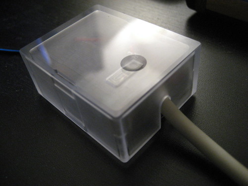
Thanks to everyone who made our first 15 deployments possible. Our peripherals are en route to Thailand, the United Kingdom, and Bolivia. Packaging these shipments, I had limited bubble wrap to secure the devices within the large boxes. However, the devices were more durable than I imagined and reached their destinations without any incidents. On the other hand, I'm not sure if the devices would survive a set of inquisitive and innocently destructive hands. As a result, we decided to build a protective cover. Thanks to Craig Lawson of Ideas Prototyped for his dedication! Craig and I have worked through a few iterations and developed a petite snap-fit cover that also fastens down the cables.

If you'd like to offer suggestions to our design, please contact me (tom.boonsiri@gmail.com).
Monday, April 6, 2009
New PCB Revision and Low-cost Proto
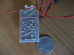
Two revisions later we have something closer to "child tamper proof". Our prototypes are on their way out to many eager children! Hooray!
If you are interested in receiving them for your pilot please send me an email to: tom.boonsiri@gmail.com. We will soon release a few prototypes for private purchase (under a G1G1 model to help finance further prototypes for the pilots). Stay tuned for more details.
Big thanks to Mike Koop and Dan Ehlers for their efforts on the latest PCB layout. Another big thanks to the guys at Liquidware/GL Interfaces for subsidizing the cost of a component.


If you are interested in receiving them for your pilot please send me an email to: tom.boonsiri@gmail.com. We will soon release a few prototypes for private purchase (under a G1G1 model to help finance further prototypes for the pilots). Stay tuned for more details.
Big thanks to Mike Koop and Dan Ehlers for their efforts on the latest PCB layout. Another big thanks to the guys at Liquidware/GL Interfaces for subsidizing the cost of a component.
Thursday, January 29, 2009
Plethy Prototype
Thanks to Ken and Mike for heading up our PCB production for our new "dongle" prototype. With our inhouse system we'll be producing a lot of 20 for distribution. For this run, we'll keep our dongle designed for through-hole mounting while a later version will be entirely surface mount. We hope to deliver the final lot by middle of February!
Thursday, May 29, 2008
IR Plethysmograph
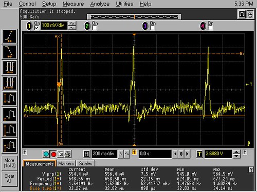
Plethysmograph is an infrared photoelectric sensor used to record changes in pulsatile blood flow from the finger. The Plethysmograph operates by recording changes in blood volume as the arterial pulse expands and contracts the microvasculature.
This circuit will provide an alternative method to visualize pulse rate for the children and remove the complications of electrode application. An enclosure will be made to help deliver a consistent view of the pulse rate and remove any motion artifacts that might be visible. The ideal enclosure could be as simple as a clothes pin. The following video also demonstrates our latest working beat detection method displaying the heart rate.
Video Demo:
Video Demo:
Wednesday, May 28, 2008
ECG Prototype 2
Tuesday, April 1, 2008
ECG Prototype 1
Jake delivered the ECG prototype 1 supported by alternative power sources (9V battery and USB). Leveraging the Measure code with a few tweaks we've fixed sampling at 4 kHz and down-sampled effectively to 500 Hz. With a buffer depth of 1100 samples only ~2 seconds worth of a beat signature is saved thus giving us an unstable beat rate. If we extend the signature to 10 seconds worth we should be able to get more stability, so we'll need to decouple the drawWaveform buffer from the buffer used for beat detection.
Nevertheless, we've delivered the first ECG prototype for the XO which will hopefully serve to gain more interest for the XO's health-related applications.
Our Demo Video
Monday, March 10, 2008
TGFG1G1
... Thank Goodness for G1G1.
My co-worker donated his G1G1 laptop for our HW development efforts. Big thanks to M. Koop for his generosity.
G1G1 Playtime: Setup network. Constructed sample probes for Mic input to investigate Measure activity's fidelity. Setup root and OLPC user passwords. Mounted USB drive.
Peripheral Development: Gary is re-creating an old Pulse Oximetry circuit. Jake has completed his 9V prototype. All final prototypes will be driven with the 5V 500mA source from the left USB port. Currently all parts procurement is covered by our generosity, but I will investigate alternate sources of funding (donations?) that does not involve filing for 501C3 tax-exempt status.
Lab Access: As recruitment efforts gain more traction on the Berkeley and Stanford campus, we hope to gain more access to HW development labs with new membership. Our current lab has restricted access which bars everyone but Gary and myself from contributing to the effort in the Bay Area.
My co-worker donated his G1G1 laptop for our HW development efforts. Big thanks to M. Koop for his generosity.
G1G1 Playtime: Setup network. Constructed sample probes for Mic input to investigate Measure activity's fidelity. Setup root and OLPC user passwords. Mounted USB drive.
Peripheral Development: Gary is re-creating an old Pulse Oximetry circuit. Jake has completed his 9V prototype. All final prototypes will be driven with the 5V 500mA source from the left USB port. Currently all parts procurement is covered by our generosity, but I will investigate alternate sources of funding (donations?) that does not involve filing for 501C3 tax-exempt status.
Lab Access: As recruitment efforts gain more traction on the Berkeley and Stanford campus, we hope to gain more access to HW development labs with new membership. Our current lab has restricted access which bars everyone but Gary and myself from contributing to the effort in the Bay Area.
Tuesday, February 12, 2008
Amplifier Design Challenges
There are two major constraints for designing an OLPC peripheral: cost and power. The laptop project has prescribed a $10 cap for all devices, and of course any design must be low power so as not to drain battery life. Right now I am designing the ECG amplifier for the XO, and I am at the stage where some decisions must be made regarding the trade-offs between performance and the cost and power constraints. The rest of this post consists of technical details, so read on only if you are interested in the engineering design aspects of the project.
Overview
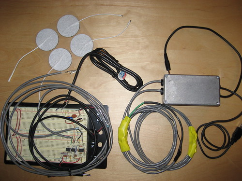
The ECG will consist of an amplifier box with an output plug going to the microphone jack and a set of two or three reusable electrodes as inputs (electrodes are an important technical consideration that we will leave for another post). The ECG application will be an extension of an existing oscilloscope program which can visualize audio jack input. The box will have a separate jack for power supply, probably from the laptop USB port.
This design is in contrast to the other possibility of microcontroller-based device, which we felt presents too many challenges in power consumption and cost. However, we support the idea of different groups working simultaneously on different approaches to the problem, and would welcome discussion with other teams that share our overall goal.
Power
Unless a separate power supply is designed, the USB port of the laptop is the most likely candidate. I knew that mic jacks supply a bias voltage, but a quick check confirmed that the voltage is too low and output resistance is way too high to think about using the bias to power a circuit.
The USB port provides 5V at a maximum of 1 amp (over all ports). Of course we want to minimize the power and so won't come close to that kind of supply current. The bigger question, though, is how (and whether) to split the supply for dual-supply op-amps. It is easy to split to +/- 2.5V with a voltage divider, but for highest CMR (common-mode rejection), the reference terminals on the instrumentation amp require low impedance, requiring an additional op-amp to buffer the new reference voltage. Although if sources of interference (i.e. 50/60 Hz power lines) are sparse or our signal processing is good then this might not be required. Single-supply op-amps can be used, but single-chip instrumentation amplifiers (discussed next) generally require a split supply.
Amplifier
Single-chip instrumentation amps (in-amps) are probably the best bet for cost, power and performance. These chips have a full 3 op-amp circuit inside, with a single external resistor setting the gain. All the resistor trimming is taken care of on the chip so component tolerance is not a big problem. The most common in-amp chip is the AD620, which provides a nice combination of cost, power consumption, and performance. However, I am looking at others, such as the INA126, which has 2 internal op-amps and is cheaper with comparable performance. Luckily they have the same pin-out and we can continue with the rest of the design independent of this choice.
Noise/interference suppression
Some additional modifications can be made to improve CMR, the primary example being a driven right leg (DRL) circuit. One op-amp can be used to tap the average of the two signal electrodes and drive the ground electrode with the inverse of this average. This is an effective way to subtract common-mode interference before it has the chance to be amplified. However, the question in this case is whether interference will be a huge problem in the environments the laptop is meant to be used. I am leaning toward including the DRL circuit, since it is hard to predict what the noise levels of the environment will be. This also applies to the question of whether to buffer the split supply, mentioned above. Again my inkling is yes on this as well.
Second stage
Is it necessary to provide a second stage of amplification? The best performance can be had using a low gain on the in-amp chip, then adding a high gain second stage after the signal is high-pass filtered. However, the mic jack provides a coupling capacitor and the audio card has up to 30dB of preamplification on the mic input, so this might be an opportunity to cut costs and let the laptop do the work, freeing up money and board space for better noise performance.
These are only a few general questions for now. In the future we will have more technical details on this as well as electrode design, modularity of the system, and software interface.
Overview
The ECG will consist of an amplifier box with an output plug going to the microphone jack and a set of two or three reusable electrodes as inputs (electrodes are an important technical consideration that we will leave for another post). The ECG application will be an extension of an existing oscilloscope program which can visualize audio jack input. The box will have a separate jack for power supply, probably from the laptop USB port.
This design is in contrast to the other possibility of microcontroller-based device, which we felt presents too many challenges in power consumption and cost. However, we support the idea of different groups working simultaneously on different approaches to the problem, and would welcome discussion with other teams that share our overall goal.
Power
Unless a separate power supply is designed, the USB port of the laptop is the most likely candidate. I knew that mic jacks supply a bias voltage, but a quick check confirmed that the voltage is too low and output resistance is way too high to think about using the bias to power a circuit.
The USB port provides 5V at a maximum of 1 amp (over all ports). Of course we want to minimize the power and so won't come close to that kind of supply current. The bigger question, though, is how (and whether) to split the supply for dual-supply op-amps. It is easy to split to +/- 2.5V with a voltage divider, but for highest CMR (common-mode rejection), the reference terminals on the instrumentation amp require low impedance, requiring an additional op-amp to buffer the new reference voltage. Although if sources of interference (i.e. 50/60 Hz power lines) are sparse or our signal processing is good then this might not be required. Single-supply op-amps can be used, but single-chip instrumentation amplifiers (discussed next) generally require a split supply.
Amplifier
Single-chip instrumentation amps (in-amps) are probably the best bet for cost, power and performance. These chips have a full 3 op-amp circuit inside, with a single external resistor setting the gain. All the resistor trimming is taken care of on the chip so component tolerance is not a big problem. The most common in-amp chip is the AD620, which provides a nice combination of cost, power consumption, and performance. However, I am looking at others, such as the INA126, which has 2 internal op-amps and is cheaper with comparable performance. Luckily they have the same pin-out and we can continue with the rest of the design independent of this choice.
Noise/interference suppression
Some additional modifications can be made to improve CMR, the primary example being a driven right leg (DRL) circuit. One op-amp can be used to tap the average of the two signal electrodes and drive the ground electrode with the inverse of this average. This is an effective way to subtract common-mode interference before it has the chance to be amplified. However, the question in this case is whether interference will be a huge problem in the environments the laptop is meant to be used. I am leaning toward including the DRL circuit, since it is hard to predict what the noise levels of the environment will be. This also applies to the question of whether to buffer the split supply, mentioned above. Again my inkling is yes on this as well.
Second stage
Is it necessary to provide a second stage of amplification? The best performance can be had using a low gain on the in-amp chip, then adding a high gain second stage after the signal is high-pass filtered. However, the mic jack provides a coupling capacitor and the audio card has up to 30dB of preamplification on the mic input, so this might be an opportunity to cut costs and let the laptop do the work, freeing up money and board space for better noise performance.
These are only a few general questions for now. In the future we will have more technical details on this as well as electrode design, modularity of the system, and software interface.
Subscribe to:
Posts (Atom)